I want to measure the pulse width of the signal on GPIO.
I have configured the timer as follows:
timer2_gpio_init(GPIO_HALL, POL_RISING);
timer2_set_mode(TIMER_MODE_GPIO_WIDTH,0,0);
timer_start(TIMER2);
And in IRQ handler:
_attribute_ram_code_ void irq_handler(void) {
irq_blt_sdk_handler();
if((reg_tmr_sta & FLD_TMR_STA_TMR2) == FLD_TMR_STA_TMR2) {
reg_tmr_sta |= FLD_TMR_STA_TMR2;
hall_pulse2.data = hall_pulse1.data;
hall_pulse1.data = reg_tmr2_tick;
reg_tmr2_tick = 0;
gpio_toggle(GPIO_LED_T); // measure signal on the scope
}
}
Here is the signal on the Scope:
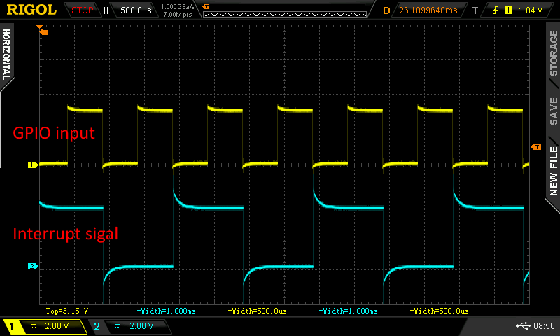
The timer is configured for POL_RISING, but the interrupt is triggered on POL_FALLING.
Is this OK?
I read the value at every interrupt for 0.5ms pulse (1kHZ frequency), which is equal to 11958.
How does it work?
Does the timer starts counting on the signal polarity rising and then on falling it triggers the interrupt?
That would make sense, but it would make it harder to do what I want
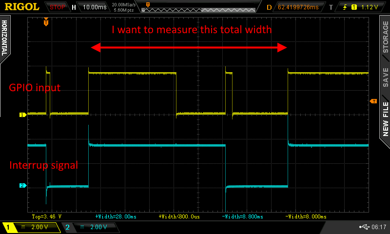
How would I measure the width of this pulse - see the picture below.
It is not a problem to read a count at every second interrupt, but what do I measure then?
I think I answered my questions myself.
After a bit of testing, I believe that the timer works as I described in the previous post.
To achieve what I want. I will use:
timer2_set_mode(TIMER_MODE_GPIO_TRIGGER, 0, 2)